Geometric Dimensioning & Tolerancing
Geometric Dimensioning and Tolerancing (GD&T) is a system used in engineering and manufacturing to specify and communicate geometric tolerances on parts and assemblies. It provides a standardized symbolic language that ensures clear communication of design requirements between designers, engineers, and manufacturers.
Key Components of GD&T:
Symbols:
GD&T uses a set of symbols to define various types of geometric tolerances. These symbols are standardized according to international standards like ASME Y14.5 .

Feature Control Frames:
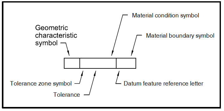
These are rectangular frames containing the GD&T symbols, tolerance values, datum references, and modifiers. They are placed adjacent to the feature or dimension they describe on engineering drawings or CAD models.

Datums:
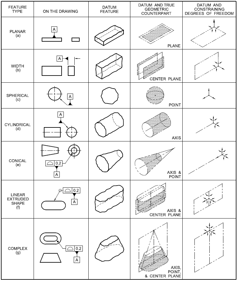
GD&T datums are reference points, lines, or planes on a part that serve as the basis for dimensional measurements and geometric tolerancing. They establish a coordinate system relative to which the geometric tolerances of features are defined. Datums are critical in GD&T because they provide a consistent reference frame for measurement and inspection, ensuring that parts are manufactured and assembled correctly according to design specifications.

Tolerance Zones:
These are specified regions around a feature within which the actual geometry must lie to be acceptable. Tolerance zones can be defined as a volume (3D) or an area (2D) depending on the type of tolerance.
